


b. Side tank clean-out doors, Quantity of five (5)
c. Sloped tank floors and drain decks for cleanliness and easier drainage
d. 14 gauge stainless steel tank access lids with vapor sealing design
e. Electronic water level controls for each stage
f. Water fill valves and solenoids
g. Dual stainless steel screens with sludge dams for each stage
h. Overflow and drain pipe with valve on each tank
i. Vapor baffle over heated tanks to retain heat
b. Schedule 10 304 stainless steel serpentine burner tubes
c. Factory Mutual gas manifold
d. Valve proof of closure switch and burner low fire start switch
e. Premium Efficiency fan motors (see General Specifications, Motors)
f. Stainless steel burner tube exhaust stacks
g. Personnel guards around burner stacks up to approximately nine (9) feet from the floor
b. Temperature gauges on heated stage pump discharge headers
c. Flanged, butterfly type pump discharge valves
d. Stainless fitted pumps (shaft and impellers)
e. Premium Efficiency pump motors (see General Specifications, Motors)
f. Schedule 80 CPVC headers and risers
g. Cam-Lock quick disconnect fittings on headers and risers
h. Snap-on adjustable nozzles
i. Counterflow make-up water systems; Quantity of two (2); Stages 4 to 3 and 2 to 1
j. Misting header system
k. Misting risers; Quantity of four (4), after Stages 1, 2, 3, 4
l. Pressure control (utilizing variable frequency controllers rather than throttling valves)
m. Bottom feed header orientation
b. 304 stainless steel conveyor shroud
c. Fiberglass full length grating catwalk
d. Entry and exit vestibule exhaust fans (epoxy coated)
e. 304 stainless steel vestibule exhaust stacks with flapper stack cap
f. Washer access platforms and lighting; Quantity of four (4)
Manufacturers names are used to indicate a source of components approved by Rapid Engineering LLC; equivalent parts or components may be substituted without notice. Customer preferences, if different than those indicated below, must be specified prior to the Contract or Purchase Order. Adherence and design to the various standards, specifications and codes is based upon our interpretation.
CSA
TSSA includes technical support documentation, electronic forms
FS01921 (08/04) / FS 09122 (06/04), along with drawings and technical data.
On site TSSA inspection is the responsibility of others.
NFPA 86C - Washers.
NPFA 86 Ovens and Furnace
NEC Article 430 Standard for Industrial Motor Controls
NEMA Standard Enclosure Ratings
UL/cUL List Control Panels UL/cUL File #E200449
UL/cUL SCCR Rating Tags
AMCA-211 performance on safety ventilation fans.
Power transmission and pinch points will be guarded per OSHA specifications as
interpreted by our engineering department.
Typical components are sourced from reputable manufacturers. Rapid Engineering LLC practices a policy of continuous improvement and therefore reserves the right to alter specifications and components without prior notice.
The pre-treatment washer length is based on the time in each stage, the part length/tunnel height and the conveyor speed. Proper drain time is essential to decrease chemical carry-over between stages and the use of process water. Carry-over can also be reduced by using a rack designed specifically for the product.
The final washer design and layout should be coordinated with your chemical supplier to assure compatibility between the major elements of the pre-treatment system.
with a 3 x 5 product opening and running a 4 long part
| Stage | Process | Legth (ft, in) | Legth (m) | Temp (°F) | Temp (°C) |
| Entry Stage 1 Drain |
Cleaner | 6,10 7,0 6,6 |
2.08 2.13 1.98 |
140 Max. | 60 Max. |
| Stage 2 Drain | Rinse | 3,0 6,6 |
0.91 1.98 |
Ambiant | Ambiant |
| Stage 3 Drain | Phosphate | 7,0 6,6 |
2.13 1.98 |
140 Max. | 60 Max. |
| Stage 4 Drain | Rinse | 3,0 6,6 |
0.91 1.98 |
Ambiant | Ambiant |
| Stage 5 Drain | Rinse or Seal | 3,0 6,10 |
0.91 2.08 |
Ambiant | Ambiant |
| Stage | Tank Gallons | Motor HP | PSI | Quanity of Nozzels |
| 1 | 396 | 10 | 20 | 112 |
| 2 | 168 | 3 | 15 | 56 |
| 3 | 396 | 10 | 20 | 112 |
| 4 | 168 | 3 | 15 | 56 |
| 5 | 168 | 3 | 15 | 56 |
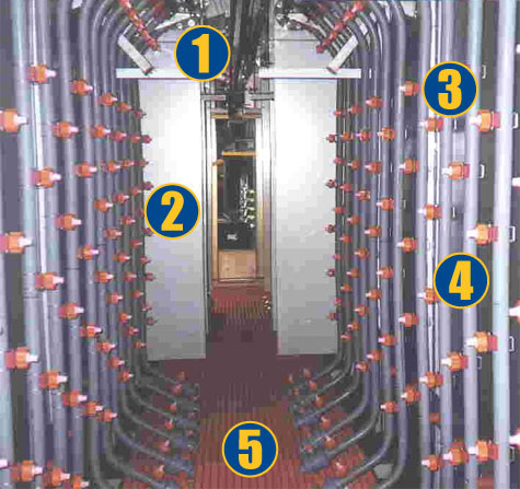
1. Conveyor shroud to reduce spraying onto the conveyor rail and trolleys
2. Profiles between stages to help contain spray in each stage
3. Snap on nozzles have adjustable angle ball tips that are easy to remove and clean
4. CPVC headers and risers
5. Fiberglass (FRP) grating for sturdy, chemical resistant support of personnel servicing
the pre-treatment washer
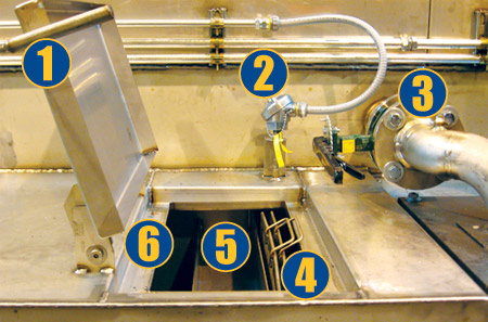
1. Extended lifting handle on heated stages
2. Tank thermocouple (heated stages only)
3. Flanged butterfly discharge valve
4. Dual stainless steel pump screens
5. Overflow trough and wire
6. Vapor seal track design that creates a natural water seal to contain vapors from leaking