Pre-treatment Spray Washer Options
Below are the many enhancements available allowing maximum flexibility to suit various processes and help maximize energy efficiency:
Counterflow Make-up Water
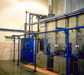
During the pre-treatment washer operation, the solutions in each tank are lost due to evaporation and "carry over" on the parts moving through the washer. "Make-up" water is introduced into the tanks from a down stream rinse stage automatically via the liquid level controls. This "counter flow" feature conserves water and chemicals. The system includes necessary solenoids and piping between stages.
Counterflow Rinse
This feature is designed to help: reduce overflow discharge of the pre-treatment washer, to improve cleanliness of the rinse process, and to extend the longevity of the rinse solutions.
Water is pumped from the last rinse tank to the preceding stage by means of a spray riser with misting nozzles. The rinse stages are replenished with fresh water from down stream stages. This “counterflow” method maintains clean rinse solutions at the exit end of the pre-treatment parts washer.
Split Top Tunnel
The split top tunnel design assists in protecting the conveyor chain and trolleys from the pre-treatment washer spray zones. The conveyor rail, chain and trolleys are located external to the pre-treatment washer tunnel. Nylon brushes are located on both sides of the “conveyor slot” and form a seal around the part hanger.
Split Top Exhaust Plenum
The roof slot has an exhaust plenum mounted the length of the industrial parts washer tunnel, parallel to the conveyor slot, to capture any mist that may be present.
Pre-Treatment Washer Access with Lighting
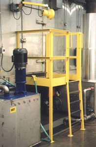
To improve serviceability of the pre-treatment washer interior, fabricated steel service platforms and ladders can be installed at access door locations and at the entrance and exit vestibules. Platform ladders are rugged structural steel construction, painted “safety yellow”.
To help improve visibility inside the tunnel, a water proof, double-hinged arm, high intensity electric light with ground fault circuit interrupt can be installed at access platform.
Stainless Steel Construction
The pre-treatment parts washer option will be constructed of stainless steel and include the following:
• 7 gauge 304 stainless steel tanks and drain decks
• 14 gauge 304 stainless steel tunnel housing
• Schedule 10 stainless steel burner tube(s)
• Stainless fitted pumps (shaft, impeller are stainless steel; other immersed parts are mild steel)
• Optional stainless wetted pumps (immersed parts are stainless steel)
• Stainless steel conveyor shroud
• Stainless steel exhaust stacks in the pre-treatment washer entrance/exit
Vapor Baffle
On heated tanks, a stainless steel baffle system can be installed over the open tank in the tunnel to help reduce evaporation and heat loss.
Misting Header System
Fresh water misting header system can be provided for the length of the pre-treatment parts washer. This system will apply a fresh water mist on the parts if the conveyor is turned off during normal production to keep parts wetted during this period.
Misting Riser System
Flash rusting can begin in approximately 60 seconds if parts start to dry in the drain zones. Misting risers are designed to help prevent flash rust between stages by keeping parts wet.
Tank Heating (Steam)
For each steam heated tank, we install a self-operating regulator and indicator. The regulator will include a suitable strainer for valve protection. Each heating coil is provided with trap, check valve and bypass line with valves arranged to permit removal of the trap for servicing. Heating coils can be valved and piped to allow removal of any individual coil for cleaning or replacement.
Each tank will be heated by a steam heat exchanger designed for the appropriate PSIG at the control valve. Temperature control will be achieved with a self-acting indicating steam control valve. Each heat exchanger slopes to its individual condensate trap and has complete piping to the control valve.
Tank Heating (Electric)
Electrically heated tanks are provided with flanged immersion heaters, complete with temperature stat, step controller, contractors, indicating lights and selector switches.
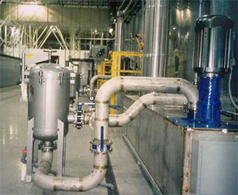
Bag Filtration Systems
The bag filter unit is equipped with inlet and outlet valves, air blow out, gauge, and drain ports. Units will accommodate single or multiple bypass and are designed for full or partial flow fluid filtering.
Reverse Osmosis System
Includes:
• One (1) Reverse Osmosis purification system
• One (1) polyethylene storage tank
• One (1) re-pressurization system
• One (1) SCRS duplex water softener
• Two (2) carbon filters
High Velocity Air Blow-Off System
A packaged high pressure blower type system will be installed at the exit of the pre-treatment parts washer. This system includes a properly sized high pressure blower, air manifolds, nozzles, hoses and hardware to efficiently blow off excess water from the parts and aide in the drying process.
Evaporation System
An evaporation system will be provided to evaporate the daily waste water or overflow water from the system. The evaporation system includes a heated evaporation holding tank, pump system, evaporator/fan module, and stack. The tank has a capacity of 200 gallons and the evaporator/fan module is capable of up to 50 gallons per hour.
Pressure Control (Pump By-Pass)
Pump discharge piping will include manually operated valves to bypass 50% of the pump discharge directly to the tank instead of to the spray nozzles. This feature will allow adjustment of the final nozzle discharge pressure.
Pressure Control Variable Frequency Drive (VFD)
Pressure control will be achieved by means of a VFD for each motor. The discharge throttling valves will not be provided. The adjustment will be controlled through the VFD and will be based on percent of pressure. The VFD controls allow for soft motor start-ups and help conserve energy. Reduced energy consumption helps provide a significant payback.
Exhaust Stacks
The stacks include roof curbs, stack spacers, rain shelters and high velocity no-loss caps on the burner stacks only. The burner tube stacks for heated stages will have personnel guards around burner stacks up to approximately 9 feet from the floor. The burner tube exhaust stacks utilize spiral pipe, typical of the industry. Other stack constructions are available if requested or if required by local jurisdictions. Stack offsets and roof flanges for irregular roofs are also available.
Controls
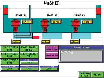
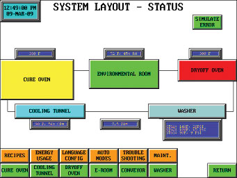
The proposed control panel includes a Programmable Logic Controller (PLC) so that integration and control of system components can be optimized, observed, and easily modified via software rather than hardware. The display is an 8 inch color, or optional 15 inch color.
Proven benefits of PLC based systems include:
• A centrally located, easy to use interface.
• A large number of control and display options.
• Alarms with text alarm descriptions
• System status for any specified parameter
• Time and date stamped alarm and error histories
• Automatic start and stop of the system functions
• Password protection for key set points and other major operating parameters
• Ethernet ready with ability to link with another computer or equipment as well as
Rapid Engineering LLC technical service department
• Ability to be linked to another computer or equipment.
• Easier capability to be upgraded to higher functional capacity.
Use of a PLC does require maintenance, including documentation, purchasing the software by the user, programming skills and, if “zero down time” is required, on-site spares of primary PLC modules and components.
Typical Touch Screens
