Pre-treatment Parts Washer Components

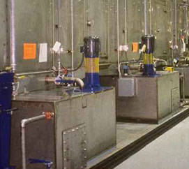
Pre-treatment Spray Washer Tanks
Industrial spray washer tanks are electrically welded inside and out, and provided with necessary structural steel grillage, bracing, pump screens, guides, valved drain, fill assemblies and overflow weirs. Pre-treatment washer tanks include automatic liquid level controls. Each tank bottom is sloped to a drain. To help facilitate tank cleaning, optional access panels are located in the pre-treatment washer tank external wall; the bottom of the access opening is flush with the tank floor.
For the length inside the tunnel, a mesh catwalk is provided to serve as a maintenance platform and as a guard to minimize accidental loss of the product into the tanks. Each industrial washer tank, for its length, is wider than the pre-treatment washer tunnel. This top section is fitted with “vapor seal” covers for adding chemicals, inspection of the tank contents and access, if required.
Tank Heating
Each gas heated, pre-treatment washer tank includes an immersion burner mounted on a serpentine tube with long radius welded elbows and returns for maximum energy efficiency and immersion tube life. The pre-treatment spray washer tank is equipped with necessary electric controls, spark ignition, electronic flame relay, valves, and other components to allow proper operation. The burner, with a customized gas manifold, is designed and manufactured with required safety interlocks to meet current insurance specifications.

Pre-treatment Industrial Parts Washer Tunnel
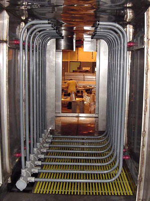
The tunnel sidewalls and top are designed to be welded together and reinforced to provide a rigid support structure for the spray piping, conveyor and product load. Optional access doors are provided in the tunnel wall (on one side) in each intermediate drain section.
Pump and Spray Piping
Piping in spray stages includes screwed compression or flanged fittings as required, sized, spaced and arranged for the best pre-treatment parts washer operation.
The spray risers are arranged in a side-by-side pattern. Nozzles in stages are clip on, “quick change” design, adjustable to provide directional control of the spray pattern. The nozzles are located on the risers so that directly opposed nozzles are aligned with respect to each other. Subsequent risers stagger the nozzle location throughout the spray stages to provide maximum cleaning action.
A non-corrosive throttling valve is provided on the discharge side of each spray pump unless VFD’s are used. Pressure gauges (stages) and temperature gauges (on heated stages) are provided on the discharge side of each pump to indicate solution pressure and temperature.
Conveyor Shroud
A conveyor shroud is provided through the length of the pre-treatment spray washer to protect the conveyor from direct spray from the nozzles.
Ventilation
Moisture from the industrial parts washer tunnel is removed by a belt driven propeller type exhaust fan located above the tunnel at the entrance and exit vestibules.


